
|


|
|

|
|

|
Flexible Circuit Capability and Overview
|
|
|
To the user
this is intended to provide information for the design, use and specification of Flexible Printed Circuit Boards of the following types.
-
Single sided circuits with or without the addition of stiffeners or rigids.
-
Double sided circuits with or without Plated through Holes [PTH], with or without the addition of stiffeners or rigids.
- Multilayer Printed Circuits.
It is also intended to provide a brief insight into MBM's capability to meet the expectations of potential customers and to explain the many different solutions to their termination problems.

|
|
|
Why a Flexible Printed Circuit
there are many clear benefits and a number of less obvious advantages in using a Flexible Printed Circuit, either in isolation or as part of a total interconnection system.
-
Cost Savings
-
How can a Flexible Printed Circuit save you money?
-
Cost savings can most readily be achieved by giving careful consideration to the interconnection needs of your equipment at the outset of the design, even before mechanical constraints are introduced. For example, the positioning of component parts and pin address on connectors etc.
-
This is, of course, not always possible. Do not be deterred, as the subsequent introduction of a Flexible Printed Circuit is still a very real possibility. The fact is that a large number of Flexible Printed Circuit designs are conceived as an after-thought as a way of overcoming other problems.
- It should be pointed out that many would be user companies fall into the trap of comparing the price (initially budgetary) of a flexible circuit with the price of a comparable (when relevant) wiring harness. They then find that the Flexible circuit price is, apparently uncompetitive and proceed no further. The costs, although higher, are much less significant as a proportion of the total cost of the installation operation.
|
|
|
Comparison of total costs for Wiring Harness Versus Flexible Printed Circuit
-
Wiring Harness
-
Identify from the wiring Schedule, the wire colour and/or coding.
-
Establish which pin of the component it should be connected to.
-
Cut wire to length.
-
Apply the coding.
-
Strip the insulation at each end.
-
Wrap wire around the pin.
-
Make the solder joint.
-
Repeat this process "N" times.
-
Bind wires into a harness form.
-
Test the equipment.
-
Fault find any wiring errors and correct.
-
Retest the equipment.
-
Printed Flexible Circuit
-
Locate all the pins of a component through the Flexible circuit.
-
Solder all the pins by hand, dip, wave or vapour phase.
-
Clean
-
Test, no wiring errors are possible once the design has been proven, (Flexible Circuit has already been inspected before despatch).

Involving MBM in the early stages of the Design Process can reap extra benefits. Here an example of a number of separate flexible circuits are used to provide a complete interconnection solution.

|
|
|
MBM Involvement at the Design Stage.
-
The range of constructions for a Flexible Printed Circuit is as wide, if not wider than that for a rigid PCB. As with a rigid PCB the choice of material used to manufacture the circuit has a direct bearing on the cost of the end product. For this reason it is important that Design Engineers and Purchasing Officers make early contact with the manufacturer to ensure that the correct material combinations have been selected for the particular application.
- A flexible Circuit can be regarded as a three dimensional interconnection device providing the electrical connections between the various component parts of an instrument or piece of equipment.

|
|
|
MBM Involvement at the Design Stage
-
The construction of a flexible Circuit is as follows
-
Single Sided Circuits
The base layer consists of an insulation material to which copper foil has been bonded. The material is then processed to create a circuit pattern. The circuit layer is then encapsulated using the same type of insulation material used on the base, access to the copper pads is achieved by pre-punching/drilling the material before laminating on the Covercoat.
- The construction of the circuit would normally be balanced; that is to say the thickness of the insulation will be the same as the covering. This type of construction provides the most reliable mechanical construction under flexing conditions.

|
|
|
Double Sided Circuits
- Double sided constructions, often employing Plated Through Holes for side to side interconnections are also common place. This type of circuit consists of 3 layers of insulation and two conductive copper layers

|
|
|
Stiffeners and Rigidisers
- Flexible circuits alone, provide insufficient support for components and connectors because of their thin cross section. It is, therefore, necessary to add local support to these areas. This can be in the form of extra layers of the insulation material (stiffeners) or rigid board, which can be bonded on using a variety of adhesives (thermally bonded or contact adhesives can both be used).

|
|
|
Multi-Layer Flexible Printed Circuits
-
Multi-layer constructions incorporate Through Hole Plating of layer to layer interconnections. There will be several layers of insulation and more than 2 layers of copper.
- The Flexible Circuit may be a simple item providing point to point interconnection, thus replacing conventional discrete wiring (with its inherent costs and production risks), but more often the Flexible Circuit will be incorporated with some other circuit technology to produce a total interconnection system.

|
|
|
Flexible Circuit Design Examples
- Below are some examples of different circuit types.
Simple point to point silkscreen Printed Circuit

|
Example of a Double Sided Circuit incorporating Screening
|
|
|
Specifications
- MBM are Accredited to ISO 9001:1994 and assessed by Lloyds Register Quality Assurance (LRQA). MBM also hold TS 157 and CAA release capability.

|
|
|
Specialist Services and Processes
- MBM employ various very specialized processes in the manufacture of flexible Circuits.
|
|

Plasma De-Smear Plant, used to facilitate 3 point contact between Plated Through Holes and Copper layers on Multi-Layer curcuits
|
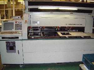
Dedicated CNC Routing and Drilling machines for accurate and repeatable hole quality

|
|
|
Availability and Pricing
Most varieties of Flexible circuits can be manufactured within 2 Weeks from receipt of Order (subject to the design having been agreed with MBM). MBM can in special cases reduce even this short lead-time.
To find out more please contact MBM Technology Flexible Circuits Division direct.
|
|
Alan Quartermaine
Operations Manager
MBM Technology Ltd
Victoria Road
Portslade
West Sussex
Direct Tel:
Fax:
E-Mail:
|

|
|
|
|
|
|
|